
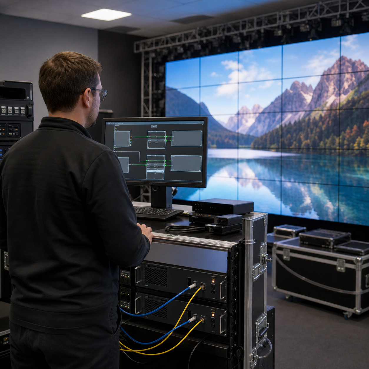
LED Display Control System Redundancy: A Buyer’s Guide
Article Summary
Learn when LED display control-system redundancy is justified and how to compare backup controllers, signal paths, failover behavior, testing, and support.
A redundant LED display control system can reduce the impact of a failed processor, sending device, network cable, or signal path, but only when the backup design covers the right failure points and is tested as a complete system. Buying two controllers does not automatically create uninterrupted operation. Procurement teams need to define the required availability, map the signal chain, compare failover methods, and agree on realistic acceptance tests. This guide explains how to specify redundancy without leaving the same single point of failure in place.
Start with the consequence of an interruption
Redundancy should be proportional to operational risk. A rehearsal screen, an advertising screen that tolerates a short service window, and a live broadcast backdrop do not need the same architecture. Before discussing equipment, decide what happens if the screen goes black, freezes, loses part of its image, or displays the wrong source.
- Acceptable interruption: define whether recovery may take minutes, seconds, or must appear effectively seamless to the audience.
- Operating hours: identify continuous, scheduled, event-only, or supervised use.
- Content criticality: distinguish decorative, advertising, information, production, and safety-related content.
- Operator presence: confirm whether trained staff can recognize a fault and switch paths manually.
- Service access: estimate how quickly the failed equipment or cable can be reached and replaced.
- Recovery priority: decide whether a full-screen image, partial output, or a predefined emergency source is acceptable.
These decisions belong in the LED display project plan before quotation. They give suppliers a measurable design target instead of the vague instruction to “include backup.”
Map the complete signal chain
A typical path can include the content source, source switcher, scaler or video processor, sending hardware, fiber converter, network distribution, receiving cards, hub boards, and cabinet data connections. The exact arrangement varies by project. Draw every active component, cable, connector, power feed, and configuration dependency between the source and the LED modules.
Then mark each point whose failure could affect the whole screen or a large section. A second processor is of limited value if both processors depend on one source switcher, one power strip, one fiber converter, or one cable route. Likewise, two sending devices may not protect a screen whose receiving-card mapping has no backup input. End-to-end mapping exposes where a duplicated component still shares upstream or downstream risk.
Choose the redundancy level by project risk
| Project condition | Control approach to consider | Questions to resolve |
|---|---|---|
| Short interruption is acceptable and an operator is present | Single control path with prepared spare equipment and documented manual recovery | Where are files and spares stored, and how long does replacement take? |
| Revenue or audience experience makes downtime costly | Main and backup processors or sending devices with a defined changeover procedure | What triggers the switch, and what remains visible during changeover? |
| Large screen with several signal zones | Segmented architecture that limits the area affected by one failure | Can an unaffected section continue operating while one zone is isolated? |
| Broadcast, live production, or closely supervised event use | Redundant source, processing, transmission, and receiving paths where justified | Has failover been tested using the actual source formats and camera workflow? |
| Remote or hard-to-access installation | Remote monitoring, backup configuration, spare path, and clear escalation plan | Which faults are visible remotely, and who can perform physical recovery? |
The supplier should translate the operating requirement into a project-specific block diagram, equipment list, switching logic, and test plan.
Compare controller and processor backup carefully
Processor redundancy may use two independent units, a main-and-backup function within a compatible system, or a switcher that can route sources to an alternate processor. Ask whether the primary and backup equipment run simultaneously, whether the backup receives the same input, and whether configuration changes are synchronized or copied manually.
- Confirm the input formats, resolutions, frame rates, color settings, and scaling used by both paths.
- Record how presets, screen mapping, calibration information, and firmware versions are kept consistent.
- Define whether detection and switching are automatic, operator-controlled, or both.
- Ask what the system considers a failure: loss of input, equipment shutdown, output loss, network interruption, or another condition.
- Verify how the primary path is restored after repair and whether returning to normal causes another visible interruption.
A backup that has not been updated after a mapping or firmware change may fail when it is finally needed. Configuration control is therefore part of redundancy, not a separate administrative detail.
Protect the transmission path, not only the controller
Signal redundancy can include paired network outputs, loop or ring arrangements, dual receiving-card inputs, alternate fiber links, or physically separate cable routes. Buyers should ask the supplier to show the exact data flow under normal and failed conditions. Confirm which cabinet or receiving card starts each path and how the screen behaves if a cable is disconnected at different locations.
Physical routing matters. Two cables placed in the same conduit, joined through one converter, or exposed to the same connector panel can share a common failure. Separate routing may not be practical everywhere, but the drawing should make shared sections visible. For permanent installations, coordinate signal routing with the cabinet, structure, sealing, and maintenance plan for the selected outdoor LED display solution.
Do not confuse signal backup with power backup
Two control paths cannot operate if both depend on one failed power source. Review the power for processors, sending devices, fiber converters, network equipment, source devices, and the display itself. Depending on the availability target, the control rack may need separate protective devices, independent feeds, or a suitable uninterruptible power arrangement. The display power architecture may need a different solution because its load is much larger.
Ask the electrical and LED suppliers to coordinate maximum load, normal operating estimates, startup behavior, protective devices, grounding, and backup scope. The LED display power-consumption guide explains why maximum circuit capacity and average energy use should be treated as separate planning questions.
Define what acceptable failover looks like
Terms such as automatic, seamless, and hot backup can hide important differences. Ask the supplier to demonstrate the visible result rather than relying on a label. A switch may create a black frame, freeze the previous image, restart the processor, resynchronize the source, or briefly show incorrect scaling. The acceptable behavior depends on the application.
Write acceptance criteria for detection time, switching time, visible disturbance, audio coordination when relevant, operator notification, alarm logging, and restoration to the primary path. If uninterrupted content is essential, use the actual source chain and representative content during testing. A laboratory statement about one device cannot prove the behavior of the installed system.
Include redundancy details in the RFQ
- Required operating hours and maximum acceptable interruption.
- Screen resolution, cabinet layout, signal zones, and content sources.
- Main and backup equipment models, quantities, firmware, licenses, and included accessories.
- Normal and backup signal diagrams, including shared components and cable routes.
- Automatic and manual switching logic, fault detection, alarms, and operator controls.
- Power arrangements for the control rack, source equipment, transmission devices, and screen.
- Configuration files, mapping backups, passwords or access handover, and version records.
- Factory and site test cases, pass criteria, evidence format, and correction process.
- Recommended spare equipment, storage method, response support, and replacement procedure.
When the risk level is still under review, request a priced base design and clearly identified redundancy options. Buyers can then compare what each layer protects and what it adds to the project.
Test failures during factory and site acceptance
Redundancy should be verified by controlled fault simulation. During the LED display factory acceptance test, disconnect or disable the agreed primary inputs, processor outputs, sending paths, fiber links, network cables, and power feeds one at a time. Record the image behavior, alarms, switching action, recovery time, and restoration procedure. Do not create unsafe electrical conditions; power tests should follow the approved method and be handled by qualified personnel.
Repeat relevant tests after installation because site cable lengths, converters, network routes, power distribution, and source equipment can change the result. The final report should identify the test point, expected response, actual response, evidence, pass status, correction, and retest. A single video of one successful cable pull is not a complete redundancy test.
Plan maintenance for the backup path
Backup equipment needs inspection and exercise. Confirm status, compare configurations, test manual switching, review alarms, inspect connectors, and verify that software dependencies remain available. Retain a current system diagram and dated configuration archive in controlled locations.
Keep spares compatible with the installed revision and identify who can authorize replacement. The LED display spare-parts checklist provides a practical way to plan receiving cards, cables, power supplies, modules, records, and replenishment without relying on an unexplained percentage.
Common redundancy mistakes
- Duplicating one box only: upstream and downstream shared components remain unprotected.
- Using the same cable route: both paths can be affected by one physical incident.
- Ignoring configuration drift: the backup contains outdated mapping, presets, or firmware.
- Assuming automatic means invisible: detection and switching can still create a visible disturbance.
- Skipping restoration tests: the backup works, but returning to the primary path causes a second failure.
- Testing diagrams instead of faults: documentation cannot replace controlled end-to-end simulation.
- Buying complexity without ownership: no operator is trained to interpret alarms or maintain the alternate path.
Frequently asked questions
Does every LED display need a redundant controller?
No. The decision depends on the cost of interruption, service access, operator coverage, and recovery requirement. Some projects are better served by a documented manual replacement plan and compatible spare equipment.
Is a dual network cable enough for full redundancy?
Not necessarily. It may protect one section of the transmission path while the source, processor, sending hardware, converter, power supply, or receiving-card arrangement remains a single point of failure.
Should failover be automatic or manual?
Automatic switching can shorten response time, while manual control may give an operator more judgment during unusual source or content problems. Many projects benefit from automatic protection plus a clear manual override, but the correct choice should be tested against the operating workflow.
What evidence should the supplier provide?
Useful evidence includes the system diagram, equipment and firmware list, configuration archive, cable schedule, fault-test record, switching video, alarm log, operator procedure, and signed acceptance results.
Specify the failure response, not just the hardware
A practical redundancy design begins with an acceptable interruption and ends with a tested recovery procedure. Map the complete signal and power chain, identify shared risks, document the switching behavior, keep both paths configured, and repeat fault tests after installation. This approach helps buyers compare proposals by the protection they actually provide rather than by the number of duplicated devices.
For a project-specific control review, send the screen size and resolution, cabinet layout, content sources, operating hours, acceptable interruption, site cable distances, power arrangement, service access, and intended acceptance tests. SXLED Display can use those inputs to prepare a clearer quotation scope and redundancy discussion.
How This Guide Was Prepared
This guide was prepared by the Shangxian Display Editorial Team using available product specifications, factory inspection workflows, recurring buyer questions, and practical project-selection requirements.
Final product specifications, certifications, warranty terms, spare-parts quantities, lead times, and installation requirements should be confirmed for the selected model in the project quotation.